Suzuki Srad Fuel Tank Pump Flange Modifications

Suzuki Srad Fuel Tank Pump Flange Modifications

A typical fault with the Suzuki SRAD tank was the pump seal arrangement on the bottom of the tank.

If the pump and flange plate were removed for any reason and then refitted, there was a big chance that with a fraction excessive tightening of the clamp bolts that the spot welded flange would distort and then the sandwiched seal ring would not pull tight against the flared opening flange of the tank.

Major problem if you had done the above, filled the tank and had fuel pouring out the bottom of the tank on a nice hot engine / gearbox casing. Very poor design by Suzuki really.

Anyway, my customer having spent a good wedge of cash on getting his tank repainted was left in the same position the first time he put new fuel in his nice newly painted tank. Upon inspection it could be seen that the flange the clamp bolts thread into had distorted and hence the seal ring was not sealing against the tank flange lip.

1394333_10201812688990600_1496320034_n

As can be seen from the image above the original set up takes the form of a 4mm thick flange that is spot welded to the main tank in between the threaded bolt positions, you may also be able to see the dimples in the tank under the positions where the clamping bolts sit through the flange so the bolts dont actually damage the tank shell. You can also see the pressed up flange around the opening that the seal ring actually seals against when the whole thing is tightened up. Clearly also shown are the positions where the spot welds have been positioned in between the drilled and tapped holes.

1451558_10201812688110578_1319495453_nAbove image shows where I have had to drill out the spot welds in the original flange in order to get the damn thing off – best spot welds I have ever removed! This took a bit of tugging and hammering to get off and the next image shows that I then had to do a little panel beating with a small aluminium block to level the panel work back up a bit.

1488167_10201812686750544_1878547800_nA little bit of flushing off and a bit of sanding down and cleaning up and we are ready to fit the new flange.

1477649_10201812687190555_1337374619_n

Laser cut, mild steel, thicker 6mm pump mounting flange offered up in place on the original tank. This will be tacked and welded in  place using a 10mm thick top plate to help soak some heat away and to help stop the new flange from distorting whilst welding.

1st we need to drill and tap out the holes. Drill out 5mm (4.8mm actually) diameter in order to tap M6. I did this using a battery drill set at low torque setting to prevent breaking the tap off in the hole. Notice that I didnt get the holes laser cut as this leaves a “hard” surface on the material which is a nightmare to thread out then, so all I did was get the laser to put a cross mark exactly where the holes come, ensuring dead accurate marking.

1461168_10201812687470562_548027505_nOnce all the holes were drilled and tapped out, a double check on the orientation and bolt the blanking flange up, sett up on the tank for accurate tack up.

1465371_10201812685430511_1213561555_n
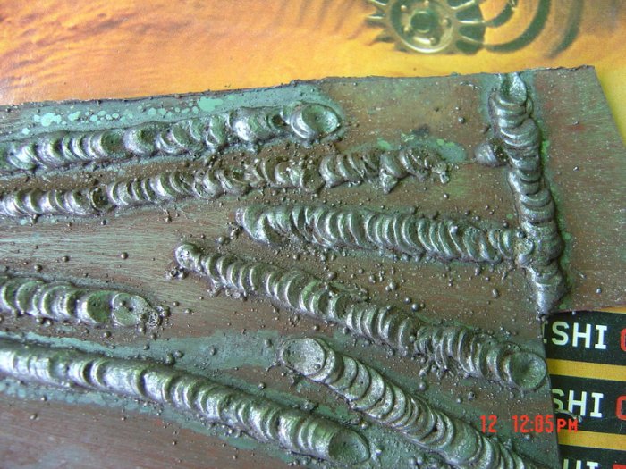
Once tacked up, I removed the blanking plate and double checked the tack up and positioning. I had to make sure that I clamped the tank panel work tight up to the flange. Unfortunately even with the new flange tacked tight up I still had a gap to fill where the original dimples in the tank are, so I had to weld as cool as possible but a large fillet size to cover the dimples.

601593_10201812684590490_1838420620_nOnce the weld had had time to cool down I removed the blanking plate, although the flange had stayed flat and level there was a bit of shrinkage in the panel work.

The blanking plate was the used as a template to make a silicon rubber seal for testing, I also had to drill the blank plate and weld 2 pipe stubs on so that I could connect an airline and pressure blow off valve.

The seal and clamping plate were bolted back in place and tightened up I connected an airline one side and a pressure relief blow off valve the other. Spraying soapy water around the welded area and then pressuring up the tank if there is a leak you can see air bubbles bubbling out of pinholes etc.

1422412_10201812680470387_1229572719_n (1)1477370_10201812683110453_1967566878_n (1)

On to dry off, clean up, bit of paint and jobs a good un!

Just waiting for the laser cut nitrile seal to clamp up and finish the job.

———————————————————————————————————————————————–

For all your Custom Car & Motorcycle Parts Manufacture and Welding / Repairs
SEE –
www.flashcustoms.co.uk
Don`t forget to email or call us for all your custom made 1 off bespoke items.

Alloy welding / repairs, custom parts, Welding Instruction.

Thanks for reading our blog – we hope this has been of use to you.
Recommended sites
FLASH CUSTOMS – Specialist Custom Car & Motorcycle Parts
Automotive LED Lights – Car & Motorcycle LED Lighting Solutions
Loaded Wallet – Discount and cash back offers

Email – sales@flashcustoms.co.uk

——————————————————————————————————————————————————————

Want to make savings on your bills?

——————————————————————————————————

Can you write a simple blog ? You too could also be earning an income from blogging!

EN_Paid-To-Blog-Banner

Ducati Oil Catch Tank

Ducati Oil Catch Tank

A nice little fabricated aluminium oil catch tank to fit up behind the head stock and between frame spars on a customers special build Ducati motorcycle.

Initially a simple card mock up was made and changed several times just to get the tank to sit tight up and at the right angle to the frame miss all parts required.

995201_614518405260671_1390513078_n

Once the mock up was complete and we was happy with it, I cut out and pressed up the tank in 2 sections of 1.5mm ns4 aluminium.

Just to make sure I tacked the tank up and we tried it in position to ensure it wasnt going to catch anything as it is maneuvered into place. Once held in position we could see what actual room we had available to us and where we could put breather, site glass, filler cap (to empty in this case), and of course the mounting points. Very little room was left and we decided to mount the tank on welded brackets to each side frame spar, this also then needed thought to be able to bolt the tank in position. The best idea we came up with was to machine top hat, blind threaded bosses to weld into the bottom of the tank. Shown below.

1382397_614518408594004_1194232634_n (1)

Now the mounting top hats are welded in we can see that there is very little room for the breather and inlet pipe, made from 6mm aluminium tube with a 1mm wall thickness.

67062_10201573501611065_1449171905_nSo above you can see that the bottom of the tank is quite “busy”, the pipes had to be welded into the bottom of the tank as there was no room above or down the sides of the tank to run flexible hoses.

1380439_10201573500891047_1419960809_nSo if we look at the other fittings on the tank you can see the black filler bung is on the top, the sight gauge is mounted half way down the tank (black with clear lens) and if the oil mist ever fills enough you will see oil in the tank.

Both of these fittings had a simple little machined threaded boss with a “flange” round the top. My customer actually provided the machined fittings, only the filler threaded fitting had very little top flange to weld to. This with aluminium can be a problem as unless we have a flange with a little “meat” on it will rapidly be saturated in heat and “blow” away before we fuse to the main tank.

Aluminium dissipates heat very quickly unlike stainless steel or mild steel, but as this tank was so small and thin it quickly became “heat saturated” and you really have to watch the heat input otherwise the weld will “flood out” and look poor as well as being uneven and have massive excess penetration into the tank.

249077_614518415260670_1364078305_nAbove you can see how small the flange was on the filler boss, only approx 2mm in section.

67062_10201573501611065_1449171905_nSo once complete and welded up the tank needed to be tested for leaks, a simple process whereby we block all the holes up, add air pressure into the tank and simply brush soapy water around all the joints and welds. If there are any pin holes then the air will bubble through. Luckily this had no such issue.

14138_10201573502131078_872299244_n

Above you can see the finished article and the basic drawing we worked to.

Now the tank is complete my customer is taking the whole bike to Italy to a specialist frame builder to have a frame built.

————————————————————————————————————————————————-

For all your Custom Car & Motorcycle Parts Manufacture and Welding / Repairs
SEE –
www.flashcustoms.co.uk
Don`t forget to email or call us for all your custom made 1 off bespoke items.

Alloy welding / repairs, custom parts, Welding Instruction.

Thanks for reading our blog – we hope this has been of use to you.

Carbon Fibre Wrapped Oil Catch Tank.

Wrapping” is becoming ever more popular in the automotive industry. Many effects, colours and designs can be achieved using vinyl wrap. This can be used to change the body colour of a car, or other vehicle, or used in business advertising for company vans, cars and vehicles.

Not only can you change the appearance of your vehicle but a vinyl wrap also helps to protect your vehicle from day to day scuffs and scrapes, swirls and scratching.

Heat activated adhesives backing the wrap material leave no real residue should the wrap ever be peeled off the vehicle and if applied correctly a stunning effect can be achieved for a lot less than a respray and or airbrushed artwork.

We came across a very good company for wrapping  vehicles and parts, they have wrapped a simple alloy catch tank for us to showcase their skills in wrapping smaller items.

The wrapping on this tank is a carbon effect wrap and is an excellent and effective finish. We simply wanted something different and this sure is, I think you`ll agree it looks absolutely awesome.

The beauty of this is that heat should not affect the wrapped finish, should the Oil Catch Tank get hot vapours through it.

John our wrapper gives a few bullet point tips for wrapping parts

  • Make sure your using good quality carbon fibre vinyl wrap
  • Measurements of the item your wrapping, do not cut direct to the size of the item, allow overlap
  • Applying the carbon wrap- clean the item or items before applying the wrap clean this by (alcohol related liquid) and wash thoroughly by cleaning this gets all the grime anything that has attatched on the object, it will remove them which will give you a smooth finish.
  • When you have measured your vinyl then at constant heat with a high temperatured heat gun the glue will then be activated and ready to be stuck to any surface ( you have to know when the vinyl is flexible enough to apply)
  • Work out the bubbles and creases bit by bit, but also making sure the vinyl doesnt skrink too much around the object.
  • Any overlap may be cut/sliced with a sharp tool
  • A lot of patience time and skill is required for a great outcome.

 If you would like help in getting your car, vehicle or parts wrapped you need to contact John email – carbonwrap999@hotmail.co.uk

www.flashcustoms.co.uk

Don`t forget to email or call us for all your custom made 1 off bespoke items.

Thanks for reading our blog – we hope this has been of use to you.

Recommended sites

FLASH CUSTOMS – Specialist Custom Car & Motorcycle Parts
Loaded Wallet – Discount and cash back offers
Cash Back – Cash Back & Money Saving offers

Buying a MIG Welder – Continued

The quality of a MIG Welder varies tremendously, dependant upon country of origin. Some welders made in eastern Europe / Taiwan / China tend to be of a lower price and accordingly of lower quality, they tend to have cheaper electronic components, don’t always last as long and spares are often difficult to get hold of.

A welder that has a higher initial cost may save you money long term as usually electronic components and wire feed and drive units are of superior quality. So its definitely worth putting in a bit of leg work before buying.

A point worth noting is that searching for a local welding supplier may be worth it as they will advise you of what spares they carry or have access to should your welder go wrong, they will more than likely be able to advise you on a purchase.

A DIY MIG Welder that is occasional use only may cost you in the region of £200 to £350 dependant on make or model. You may also consider searching on-line or in local adds (Gumtree for example) for a good used MIG welder. A used welder that has been appropriately maintained and cared for might be more than sufficient in meeting your needs and come at a price you can afford. However, beware as a good second hand MIG welder will command good residual value even more so if it is a single phase 240v 3 pin plug supply that will run from a 13 amp household socket.

Features to look for in a MIG Welder may be :- ease of use, large or small torch, “euro” torch connector, size of filler wire reel, portability (is the welder on castors or light enough to lift and move around). Does the welder have a series of rocker switches, giving combinations of output amps, or does it have a dial to increase output amps (which is infinitely more adjustable than rocker switches). All of which may make for easier use.

The material thickness will determine the amps needed for the MIG welder you are considering.

The following shows maximum steel thickness for a butt weld based on amps (approx):

  • 90 amp, 2.0 mm
  • 110 amp, 2.5 mm
  • 130 amp, 3.0 mm
  • 150 amp, 4.0 mm
  • 180 amp, 5.0 mm

Keys to Using a MIG Welder

A MIG welder works through the creation of an arc between the parent metal being welded and the wire electrode. The arc creates the weld which is sealed and protected from elements by shielding gas being fed to the arc. A MIG weld generates a lot of heat and light and the welder must wear a protective shield to protect his or her eyes from ultra violet rays.

The Difference between TIG and MIG Welding

TIG welding uses a tungsten electrode. The electrode does not burn off or melt during the welding process. MIG welding uses a wire, which melts off into the weld pool. MIG welding was developed in the 1940s as a way to bind aluminum and nonferrous metals while TIG welding has been developed as a more specialist form of stainless welding steel, aluminum, copper and magnesium alloys.

Safety

One of the basics related to MIG welding is the observation of safety procedures. MIG welding uses a torch assembly that holds a consumable wire electrode that creates the weld. The welder must maintain a short arc in order for the weld to be effective. Wearing a safety shield and ear plugs and not wearing loose, combustible clothing are essential to a safe working environment when using a MIG welder.

Competency in MIG Welding comes when the operator can “set up” the machine for a particular welded joint.

Set up meaning that he or she can set the variable parameters of the welding machine (wire feed speed, amperage, gas flow) and handle the torch assembly accurately to maintain an even fillet of weld, which has sufficient penetration into the parent metal to melt and mix the molten parent and filler material into one,creating a good strong weld, and also have the skill and knowledge to maintain correct torch angles, distances from the welded joint and speed at which the operator moves the torch along the welded joint.

A MIG welder can be very useful for some car projects.

  • Floor panels.  Floor repairs are common particularly on older cars where the effects of water ingress into welded joints rapidly combines with road salt and damp atmosphere to speed up oxidation (better known as corrosion or rust).
  • Tube frames. Roll cages for racing, space frame chassis and chassis rail repairs.
  • Exhaust repair. Ideally suited to MIG welding, why replace an exhaust silencer box when you can MIG weld a “patch” on it stop gases leaking out
  • Bodywork. Welds on the bodywork can be very difficult for a novice MIG welder to produce successfully. This is mainly down to lack of skill in controlling heat input and distortion, although as your skill level increases this will be possible.

Thanks for reading our blog – we hope this has been of use to you.

Recommended sites

FLASH CUSTOMS – Specialist Custom Car & Motorcycle Parts
Loaded Wallet – Discount and cash back offers
Cash Back – Cash Back & Money Saving offers

What to look for when buying a MIG Welder

At some point or other those of us that “tinker” and modify cars or motorcycles, off road vehicles, race and track day cars and motorcycles will need to “weld” something, even if its only a simple bracket, or repair patch on a sill or chassis.

There is no getting around it that having the skill and equipment to weld small parts would be very useful in this instance.

A MIG welder is typically used in the automobile repair & fabrication industry. The process of MIG or metal inert gas welding involves a consumable wire electrode (fed through a torch assembly) & a supply of shielding gas (again fed through a torch assembly)to protect the weld. This differs from TIG welding, which makes use of a fixed, non-consumable tungsten electrode that produces a high energy arc. The method is rarely used outside, due to the effect of breeze blowing away the shielding gas, but is common inside a workshop or automotive repair facility.

Here is my beginners guide to selecting the right MIG welder for your needs.

  1. There’s lots of things to think about, electrical supply, space, where you will be welding, what you will be welding, budget and lots of more
  2. Another thought is that anyone with no experience in MIG welding really ought to seek professional advice and at least do a bit of research on MIG welding before jumping in with both feet. Please don’t just go out and buy the first MIG plant that you see.
  3. Take some time and consider what it is you want to be welding, will you be wanting to weld for example a modern-ish car (monocoque  chassis) or a vehicle such as an off roader with a  separate chassis. For a modern car with relatively thin body panels a Mig welder of approx 100amps range may suffice. For heavier chassis repair work a Mig welder with a 150amps range or more may be required. Certainly if you are going to be welding gates, railings, or any such thicker material a MIG welder with an output of 180 / 200 amp output may be required.
  4. So think about what use you will be needing the welding plant for, not just your budget, it would be false economy just to opt for the cheapest brand / welder and expect it to work miracles and weld everything in the world.
  5. Most “DIY” MIG welders will be supplied from a 240volt, 13 amp household socket. This tends to be the case up to approx 180 / 200amps, dependant on welder, make, model, specification etc. Any higher (or in some instances less) and you may need to look at installing a 16 amp or even 32 amp rated socket.

  • Over the years I have owned at various points several MIG welders from DIY to 3 phase industrial welders, I started off with a little Sealey mini MIG 100 amp set, this worked fine for basic bodywork, sill repairs, valance repairs, and single skin welding, and although in those early days there were not “gas less” MIG sets on the market I used to run this set with shielding gas – from a pub bottle. This was co2 – carbon dioxide used in the pub trade. Although a most basic set with only 4 settings it worked well once set up correctly.
  • Once I got into some other modifications and repair work I brought a Clarke 180amp “turbo” (fan cooling) single phase MIG set, again running on co2 pub gas, this worked great on heavier thickness’s, 3 & 4mm chassis plates, land rover repairs and welding new floor pans in VW beetles. Again this only had 4 heat or “output” settings with adjustable wire feed.
  • Although many people say that they can weld, the real difficulty with MIG welding is that it can look a “nice” clean, even fillet and yet still be a very poor, “weak” weld due to lack of penetration into the parent metal. In effect the weld “bead” sits on the top of the material being welded. This can be caused through lack of heat input, incorrect torch angle, weld contaminants (paint, grease, under seal, corrosion etc), lack of operator skill. This is particularly important when welding critical parts / support structures. I always say “set” the welding plant parameters up using a piece of off cut or scrap material to ensure your weld is good and strong, before continuing to weld your actual job.
  • Further to this “professional” MIG welders that I have used over the years up to 3 phase supply (3x 240v supply), 400 amps a “Fronius” electronic, programmable machine with LED touch screen controls and very technical parameter set up and control was by far the best (also by far the most expensive).

Considerations of cost and quality of machine, reliability and access to spares is another important factor in making a purchase. We all look at the dreaded eBay for prices and varying types of the product we are looking at buying. I would advise that anyone buying a MIG welding plant complete some research first and  DO NOT in any circumstances buy the cheapest machine you can see on-line.

THINK ABOUT – What you need the welder for, is it a common make or brand, can you find feedback or reviews about the machine you are interested in, can you get spares for it (we will discuss this later), will the machine rating be adequate for your welding – e.g. if you are welding patch repairs in cars will the machine weld for more than 10 minutes or so without overheating and cutting out?
This is what we call “duty cycle time” for example the manufacturer may state “duty cycle 10% at 75% max amperage. Therefore if your welders maximum amperage is 100 you can weld at 75amps for 10% of any time period (e.g. 6mins in any 1hr). This may be absolutely fine if you are completing spot welds, short stitch welds or small welds in between “setting up”. This is typical of cheap MIG welding machines for DIY use.

You may need to check that your power supply where you wish to weld is adequate – be careful to check specification of welding machine before purchase as I have seen some put the supply rating (e.g. 16amps) at the bottom of the spec listing. This means that the machine will not successfully run from a standard 3 pin 240v 13amp household socket.

Buy a machine with good ratings and feedback , if unsure speak to your local welding supplier (search yell.com), dont be frightened to ask for advice – you may not buy a machine from them but if they are business “savvy” they will do what they can as if they are helpful you may well go back to them for spares.

On the subject of spares – typical spares you may need are:- Contact Tips, filler wire reels, gas shrouds (sometimes called nozzle), in some cases disposable gas bottles (for shielding gas), if your machine breaks down:- common items needed may be gas valve, contactor, switches, torch assembly, torch lead, torch lead liner.

Finally, make sure you buy a welding plant from a reputable dealer with a warranty.

If you require any help and advice in welding related issues please  email us directly at sales@flashcustoms.co.uk

We are specialist custom parts manufacturers, Welding, Machining and Fabrication are our forte

Thanks for reading our blog – we hope this has been of use to you.

Recommended sites

FLASH CUSTOMS – Specialist Custom Car & Motorcycle Parts
Automotive LED Lights – Car & Motorcycle LED Lighting Solutions
Loaded Wallet – Discount and cash back offers
Cash Back – Cash Back & Money Saving offers