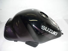
Modifications to the Suzuki Hayabusa fuel tank is required by our customer to enable him to get his head down lower underneath the “bubble” of the lowered screen. Thus reducing drag to enable him to go for a speed record on his Motorcycle.
This task was particularly difficult as not only do I need to approach the task correctly I also need the vision to see what the tank needs to look like in the end.
Sensible considerations need to be thought about before I put a cutting disc anywhere near the tank –
1 – Shape and form of the tank now
2 – Shape and form of the tank when modified
3 – Ways in which we can chop the tank and reduce the amount of welding during reassembly
4 – Heat input and distortion during reassembly
5 – Making sure that cutting and shut lines are on a natural edge, form or pressing mark where possible
6 – Re-instatement of drain tubes for filler neck
7 – Maintaining the shape and form of the tank bottom – ensuring refitting and alignment accuracy.
All of the above needs to be considered along with actual end product shape that the customer wants, how we undertake this tank modification may affect how much skimming with filler material and painting is required. Obviously the less the better as this will help both keep the tanks weight down and also the cost in terms of time and materials to “finish” the tank.
This tank is a pretty big and bulky affair, I have the option of cutting away the internal baffle pot in the filler neck to reduce the height even further as the tank will only ever be filled with race fuel via a fuel can. The overall profile looking from the bottom of the tank needs to be maintained – hence as I weld the modified top I will need to strengthen the base with small box section to help prevent the shrinkage caused by welding the top panels from distorting the base panel. If I didn’t do this it may cause the mounting points to move and also if the base panel actually distorts it may then also conflict with the intake system on the underside.

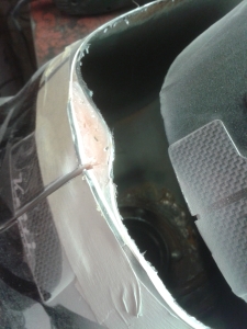
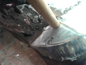
The image shown above and left gives an indication of the first “cut” line. How did I decide upon this?
The tank has “natural” form lines from original manufacture and it was easy to decide where I wanted to cut it. However, this also needed to tie up with the foresight of how the tank would go back together and if cut along these marked lines would I be able to fit the parts back together once a “slice” had been removed from the tank to get the top down lower.
With tank chops it is never easy to predict exactly how the job will go until I have actually removed some material. But, it is crucial that a good insight, skill and working knowledge be applied to the whole job planning before cutting anything commences.
Reasons for this is that if I cut wrong then I could be making myself a whole lot more work trying to put it back together later, typically this is true if I then have to start adding in more welds or making infill panels to weld into gaps left.
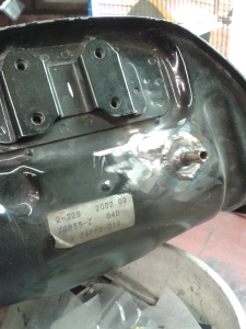
Another thing to remember also is that an awful lot of tanks have at some point been repaired, as can be seen is the case with this one. Looks to me like a very unlucky rider may have had an accident and smashed his marbles into the back of the tank. Just hope they were steel ones! See the area of filler material added in the image below.

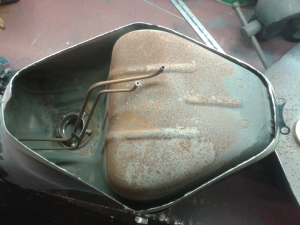
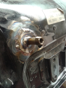
Before being able to completely remove the sliced of lid of the tank the drain tubes have to be drilled out (shown above). Then the top of the tank can be removed, revealing the inside condition of the tank. Which in this case is only surface corrosion as its obviously been sitting open for some time with no fuel in it. This one is in reasonable condition.
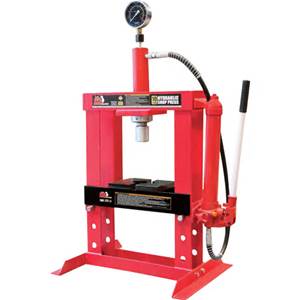
Now a major part in modifying existing tanks like this is the fact that they are generally “Stamped” or ” Pressed”. Normally in 2 sections a top and a bottom. The pressing process normally starts with a single sheet of material which is inserted into a hydraulic press with matching top and bottom die tools. Once inserted the material is subjected to large hydraulic forces when the top and bottom die come together to “stamp” or “press” the panel into the desired shape. See example below –
 Sourced from – www.learneasy.info
This process obviously puts stresses and strains in the formed material shape, not a problem for this tank that will be assembled on a production line where the two halves will be joined, typically by electric resistance welding process all the way around the bottom flange.
However, from my point of view as a sheet metal worker about to cut and modify the original tank, these manufacturing stresses and strains can cause me a headache when trying to reassemble the tank and then butt weld or lap weld the new joints. And the reason for this is that I have no idea how the material will react to heat input from welding until I actually start reassembly, tacking up and welding. The reason being for this is that the metal being no thicker than about 1mm will actually bend and distort the minute any welding heat is applied. This can cause the problems of buckled and mis-aligned joints. Increasing the chance that the finishing process will involve skimming the tank with a thin layer of filler material to flush and level / smooth out the metal ready for painting.
 Initial cutting, showing the “lid” dropped back on the tank.
Where the diagonal line of masking tape is I have actually made another cut line to allow me to be able to shape the panel inwards towards the centre line of the tank.

This image now shows roughly how much “drop” has been achieved by slicing a triangle of material out of both sides of the tank. Approx 2.5 inches at the rear most position back to nothing at the front of the tank. See how much the top has dropped down. If I now remove the baffle tube from the filler neck I can get about another inch which will leave about 10mm clear between the underside of the tank pressing (which clears all the intake) and the underside of the top panel.
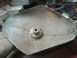
 Images showing the underside of the filler of which the small diameter baffle tube will be chopped off to gain a bit more drop on the top panel.
 Here showing the tank with the lid just sat back on, now you can see I have some panel beating and reshaping of the side scallops to blend in with the contour of the top panel. The shaped metal under the masking tape and towards the back of the tank will require shrinking to get it to “pull” in towards the centre line of the tank as well. This will be achieved by manually using a block or “dolly” and a planishing hammer. Good old bit of elbow grease! What I have to do is hammer this down to the block held behind the panel and effectively “shrink” the material to get it to pull in. There is an art to this as if inexperienced many people will “thrash hell” out of the metal and effectively end up “stretching it” which is what we dont want. Careful and gentle hammering will improve the chance of the metal molecules overlapping and “shrinking” in. If I cant get enough by using dolly and planishing hammer, some heat will need to be applied.
Heating mild steel to a cherry red and then allowing to cool down will “shrink” it. Theory behind this is the fact that when steel becomes hot all the molecules become exited and bounce off each other, hence expanding; upon cooling the molecules calm down and pull in tighter together and effectively shrink the material. Rule of thumb is that steel always contracts that bit more than it expands – hence achieving the desired shrinkage.
 Planishing the material to shrink it
And below heating the material to shrink the edge in a bit.

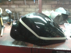
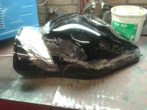
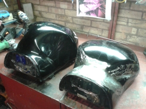
 Just a comparison above of the original and chopped down tank.
 So once I was happy with the general shape of the panels I proceeded to tack the top panel up to the bottom section. Care had to be taken to make sure that the butt weld joint preparation was set flush with minimal gap between the two edges. This is a critical stage as the more time and effort spent at the set up stage the better and easier the welding stage will be.
Its also important that as I want the tank to be even side for side, some basic measurements along the weld joint were taken before tacking up the joint to ensure some symmetry once finished.


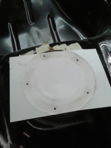
Once the tank was at the above stage the hard work really begins. I needed to effectively “blend” and “fill” the gaping open areas of the tank. Now to start with some simple paper and card templates were made up. This shape was then transferred onto metal and the piece cut out. The actual metal pattern will need lots of shaping, trimming and trial fits to get it to sit and look right. Again the tools of the trade for this are the trusty Planishing hammer and dollies, pinch rolls, bossing mallet and sand bag.
 You will notice that I have used lined paper for a basic template and also numbered up the lines to give me a better degree of accuracy and symmetry.
 Template laid onto steel ready to be cut out. Note the extra 10mm line around the outside of the template. This I have added to allow for a “joggle”, this will slip under the metal at the front of the tank and help maintain some shape and act as a guide when inserting the infill panel. Although I have one template this will be cut into 3 panels to allow for easier shaping and fitting to the tank.
 Pinch rolls are used to give some required form to the infill panel. As you can see the 2 black lines represent cut lines where I will chop the panel into 3 sections for ease of fitting.
 Shown above the infill panel with some rough shape. I will now chop this into 3 parts and start further shaping and trial fitting starting with the top panel.
 Once shaped the top panel will be joggled around 3 edges ready for fitting. Additional shaping and forming will be required after as the joggling process will pull some of the original shape out.
Once happy with the shape I clamp the infill panel in place and tack it in a couple of places and recheck fit to make sure that I am happy with the fit up.


Top panel in and work starts on shaping, forming and trial fit up of each side infill panel.


Once infill parts are shaped and trial fitted (this process may take half a dozen attempts to get good fit) then I can tack up.
 And here you can see the top and right infill tacked up in place, just the left hand side to complete.

So all tacked up and ready for welding, what process and why?
I will be MIG (Metal Inert Gas) welding the joints on this tank. Reasoning behind this is the fact that the tank is made from thin – about 1mm thick mild steel. If I use MIG  (Image taken from – www.mechanicalengineeringblog.com)
I can maintain minimal heat input and adding filler material so that I dont blow through the thin material. If I was to try try and use the TIG (Tunsten Inert Gas) welding process,
(Image taken from – en.wikipedia.org)
this is much slower and puts more heat into the job and I would not be able to add filler wire quick enough to fill the joint before the metal was melted away. I could also try and use the MMA (Manual Metal Arc) welding process (Image taken from – www.steelconstruction.info)
but this would be too hot and melt away the tank metal before any filler material could be deposited. I could gas weld the tank if I had the correct oxy-acetylene equipment and this would indeed be possible as like MIG you can control the heat input easily (if experienced in gas welding).
MIG welding is my preferred method as this gives me control of heat input and control of the speed of filler wire input, it also allows me to “fill” some gaps and many other “parameters” that I can manage to help complete the job successfully.
Using the MIG welding process to complete this task still needs a large degree of skill and understanding of the actual process and welding techniques to be used. For this job I use a technique called the `Pull` Technique, in which you actually pull the torch from left to right (if your right handed – vice versa for left handers); I also pulse the weld -this means to weld in short bursts and by allowing less than a second between pulses for the steel to cool down I can still ensure that each “burst” melts into each other; sealing the tank . The longer you leave it the more chance you’ll have of cold joints and pinholes between the welds. By utilizing this method we minimise heat input and have the best chance of not blowing through the thin sheet metal.
 This image (taken from http://www.mig-welding.co.uk/thin/stitch-weld.jpg) clearly shows the effect that you should end up with. Now not only do I use this process I also fill the tank with Argon gas, this is an inert gas and shields the underside of the weld from atmospheric attack. This should leave a nice clean penetration bead on the inside of the tank.
 Underside of weld should look something like this. (Image taken from http://www.mig-welding.co.uk/thin/stitch-underside.jpg).
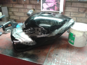
So theory into practice and the following images are what I ended up with.


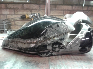
Even with all the effort and knowledge to complete this job, there are still the unknowns of how the stamped material will react to the heat input from welding. There will still be buckling, bowing and distortion to some extent. This often ends up with a butt weld that has been set up flush, distorting on one side and either a “lump” or a “dip” one side of the welded joint. This can be seen slightly on the last image shown above just under the end of the Suzuki Logo. As I cant get into the tank now to be able to dolly this out, a thin skim of filler will be required.
Main tank done and now I have to complete the drain pipe welding. Shown below.


So once everything was welded up, pressure testing the tank to check for leaks is critical to ensure a fully sealed tank.
I had to make up some flanges and seals to pressure test this tank as I didn’t have the cap or pump assembly to fit and bolt in place to seal it.

So from the template I made up a steel base plate and silicon rubber seal. I could then insert my pressure and blow off valve assembly into it. The filler flange was sealed in a similar way with a pre-made plate and seal arrangement of which I have loads of differing sizes that I have made up for previously tested tanks. If I didn’t have the blow off valve in place I could easily blow the tank up into a balloon shaped item if excess air pressure is used. I usually only use a 1 bar blow off valve (about 14 PSI), this is quite adequate. Once pressured up I spray all the welded joints with a mixture of fairy liquid and water. If there are any pin holes this shows up as bubbles on the outside, which I can then spot up.
Sometimes the “spotting up” is the tricky bit, as if there are pin holes or mini fractures anywhere in the metal or weld areas once I apply heat and filler material to it to seal it by welding, the metal expands and contracts again. Sometimes this makes the problem worse and I end up “chasing” a pin hole or hairline fracture along the edge of the welded joint.
The finished item ready for the paint shop.


 Another job done!
We look forward to keeping you up to date.

For all your Custom Car & Motorcycle Parts, Manufacture and Welding / Repairs
Don`t forget to email or call us for all your custom made 1 off bespoke items.
Alloy welding / repairs, custom parts, Welding Instruction.

 Once complete to the correct depth the next stage was to “planish” the panels to remove as much of the distortion as possible. This was completed with a Planishing hammer and an aluminium block.


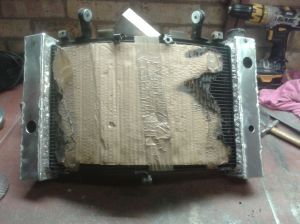
 The customers requirements with this radiator was to chop off the end cans and manufacture custom made larger end cans with a specific pressed pattern to match up with the pattern machined into the ends of his fork clamps .
 Here we go then no turning back now, 4.5 inch grinder with a 0.8mm thick cutting disk. Cuts through most general metals like butter. Shown above then is the first end can sliced off, revealing the ends of the core channels and the end plate. Now what I have done is cut the end can off approximately 10mm from the sealed flange. I have made the new back plate with a slot cut out to neatly slip over the small “stub” left. This means I can weld around the inside of the can back plate to the stub – as shown below.

 Above shows the first “test”piece that I set up using 10mm plate and small “slices” of steel and 3mm round diameter bar. Trial and error with this using some scrap aluminium gave me the definitive design and dimensions I needed. I then proceeded to make the “actual press tool”. The result is shown below.

 The image above shows the first end can panel work positioned and tacked up to the back panel. Its important for a good weld that all these panels are tacked up in what we call an “Outside Corner joint”. Shown below.

 Pipe fittings welded in place complete with new mounting bosses to pick up on the third fan bracket.
 Fans Mounted back on to check fit.
 And after testing – pressure tested to 15 psi (just over 1 bar) and a bit of cleaning up, this was the end result. Hopefully it will look as good painted and on the bike?

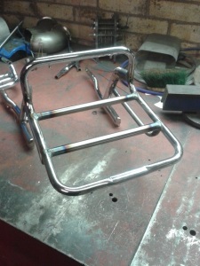
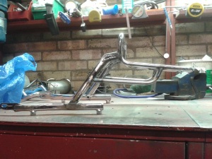
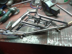 Braced up ready for cutting out unwanted parts and adding new support tube frame and blending in work. ready for dipping and re-chroming.