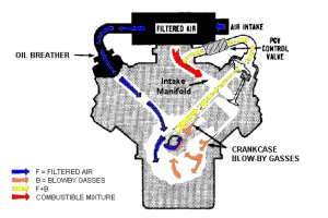
Now days on the vast majority of road going cars and vans a crankcase breather system or crankcase ventilation system is used to improve emission levels. In order to affect a controlled system a PCV (positive crankcase ventilation) valve is used to monitor the pressure in the crankcase and as this becomes too high this valves releases the excess pressure into the intake system. One thing to understand is that all internal combustion engines “leak” a small amount of combustion charge past the piston rings. When introduced into the intake system (via the PCV valve) this charge of leaked combustion gases will generally reduce the main intake charge or fuel and air mix, thus reducing the efficiency of the intake charge. This will cause loss of power and in worse case scenarios “pinking” and “detonation”.

It is common knowledge that all internal combustion engines (even when new) will have a certain amount of “blow-by” past the piston rings (a mix of acids and water vapour – combustion by products), which if left stuck in the crankcase will increase crankcase pressure leading to issues affecting the engines performance such as:-
- Reduced efficiency of oil scraper rings – creating increased oil consumption
- Starting problems and uneven idling or “rough” tick over.
- Blow-by gases causing oil contamination, “sludging” and increased engine wear.
- Weakened fuel charge, causing ignition retardation and power loss.
- Blow-by gases will escape through the easiest route possible – filler cap, dipstick or blow past oil seals.
All of the above may affect engine efficiency and performance.

On understanding the above you may now realise why a good breather system is needed on a race or high performance engine. In general terms for this application any “blow-by” gases are taken away and not fed back into the intake system but directed to a dedicated “oil catch tank”, sometimes known as a “breather tank”. This way the crankcase gases are filtered through baffles and oil, waste contaminants and pollutants “settle” to the bottom of the tank whilst cleaner air is then passed through a filter back to atmosphere.
Sometimes this oil and contaminants from the catch tank can be fed back down into the sump to be mixed with existing oil, its important to remember if this is the case the returning oil must be returned to the sump at a level below the normal level of the oil in the sump, this is because if it was returned above this level the positive crankcase pressure would blow the oil back up the drain pipe back to the catch tank. Obviously draining oil back to sump will create the need to change the oil much more regularly.
This blog is aimed at giving a basic understanding of a PCV breather system; in reality this system is a little more complicated in its operation but I have tried to simplify it to aid understanding.
Thanks for reading 🙂
Recommended sites
Haynes Internal Combustion Engine Model


